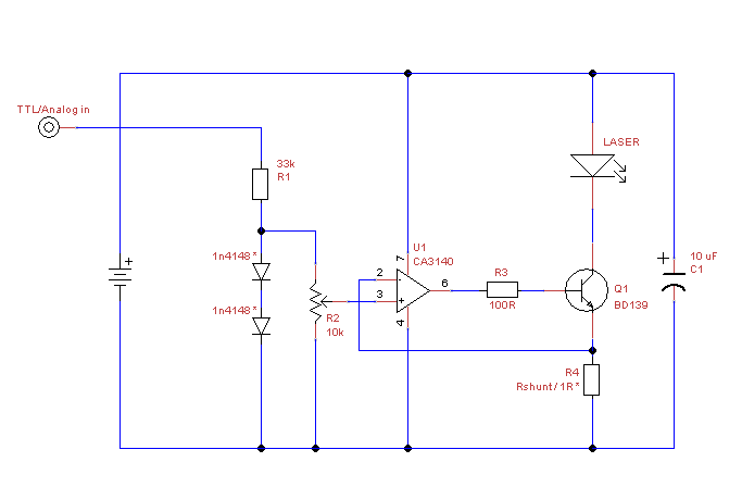
TTL/Analog controlled opamp based current source
This current driver is an extention to the adjustable current source published previously.
For details on component values, design considerations and such, please refer to the opamp current source previously explained.
The additions to the circuit to allowTTL or analog modulation of your lasers are fairly simple:
Instead of running the reference from the power supply, it is not powered fro the input lead. The maximum set voltage is still limited to about 1.2 volts by the pair of 1n4148 diodes, but is now controlled by the input. R1 and R2 form a 3:1 voltage divider, translating the input voltage of 0-5 volts down to 0-1.25 volts. R2 is still used to set the maximum current going tot the laser. The calculations for the shunt resistor are identical to that of the unmodulated version.
A 10 uF capacitor was added over the supply voltage to handle the quick differences in load power when running laser shows. The input voltage is compatible with an unbalanced line from any ILDA controller.
Due to the speed of the opamp and the transistor used, this circuit can be used with virtually all laser equipment, running it at 50 kHz/pps or more poses no problem for this driver. Also, it can be used for PWM dimming of the laser at speeds up to 100 kHz or so.
NOTE: this circuit does not have any compensation for lasing treshold or non-linearity of current/output curves for the laser diode (or dpss module) used. If you want great linearity for analog shows, you need to address this issue either in the compensation amplifier or driving software.
Despite being intended for laser use, the circuit can also be very usefor for driving power LED's from a microcontroller. Both analog input from a DAC and digital PWM are possible.
Finally: A picture of this schematic employed in a laser projector. This schermatic features 2 of these drivers (one for 660 nm straight diode and one for 532 dpss green). Note that the BD139 transistors are heatsinked in this setup as it is driven from about 10 volts with output currents of up to 300 mA.
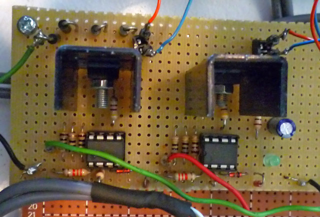
This particular example uses 3 10 ohm resistors in paralel to for a 3.3 ohm shunt resistor. Also, 470 ohm was used as the base drive resistor, but this is not required and the depicted 100 ohms will just fine. A couple of 1n4007 diodes are also visible, these are used to drop the voltage a bit so the transistors will dissipate less heat. The green led is simply a power-on indicator and is not shown in the schematic. Note that the picture shows 2 complete amplifiers, and these ones do not have the R2 potmeter to set the maximum current, as that is all dealt with in the compensation amp driving it.